
LUCKY ROULETTE/ROULETTE EXPLOSION
SERVICE MANUAL
for Interblock Service
-This manual is for ib engineers-
This manual is intended to provide the service method for “Roulette Explosion” and “Lucky Roulette”.
Version LRO-TEC-S-008
Dec 16, 2022

The safety words of DANGER, WARNING, and CAUTION are used in this manual to indicate hazard levels. Please understand each meaning to handle the machine safely.
It warns of the immediate hazards which WILL result in severe personnel injury or death.
DANGER
It warns of hazards or unsafe practices which COULD result in severe personnel injury or death.
WARNING
It warns of hazards or unsafe practices which COULD result in minor personnel injury or product/property damage.
CAUTION
WARNING
- A periodical maintenance and/or replacement parts are required in order to handle the mechanical movements.
- Please understand that it may yet fail to operate due to troubles, if the maintenance described herein is not performed.
WARNING
- Risk of Electric Shock.
- ARUZE makes no warranty as to accidents (including failures) caused by improper grounding.
NOTICE
Be sure to check this information on the installation environment before installation.
The nameplate is located on the bottom.
For the customers
This equipment has been tested and found to comply with the limits for a Class A digital device, pursuant to part 15 of the FCC Rules. These limits are designed to provide reasonable protection against harmful interference when the equipment is operated in a commercial environment. This
equipment generates, uses, and can radiate radio frequency energy and, if not installed and used in accordance with the instruction manual, may cause harmful interference to radio communications. Operation of this equipment in a residential area is likely to cause harmful interference in which case the
user will be required to correct the interference at his own expense.
You are cautioned that any changes or modifications not expressly approved in this manual could void your authority to operate this equipment.
All interface cables used to connect peripherals must be shielded in order to comply with the limits for a digital device
pursuant to Subpart B of part 15 of FCC Rules.
This device complies with part 15 of the FCC Rules. Operation is subject to the following two conditions:
(1) This device may not cause harmful interference, and
(2) this device must accept any interference received, including interference that may cause undesired operation.
A. Definition of Safety Words 2
D. Installation environment for tracking ball 2
1. Machine check list (Lucky Roulette) 4
2. Inspection, setting, adjustment of the machine 5
2.4. Cleaning inside cabinet 6
2.9. Ball pocket wall condition 6
2.13. Ept Sealer of the canter cap 7
2.15. Clearance between bank and pocket 7
2.16. Gap between bank and pocket 7
2.18. Roller Assy and motor (Wheel) 8
2.19. Wheel sensor condition 8
2.20. Projector filter condition (VPL-FH700L) 9
2.21. Tracking ball condition 10
2.22. Compressor and filter condition 10
2.23. Separator filter(corner) condition 10
2.24. Air pressure and ball rotation 11
2.25. Air regulator condition 11
2.28. Electric air sensor condition 11
2.30. Live camera condition 12
2.30.1. Things to be required and preparing camera setting 12
2.30.2. Procedure for ball tracking setting 12
3. Chi-square (Random Number) test 15
3.1. Basic knowledge of chi-square test 15
3.1.1. What is chi-square test? 15
3.1.2. What is the standard? 15
3.3. Setting related self chi square test 15
3.4. Judgment of internal chi square test results 16
3.5. How to perform chi-square test before shipping/installing 16
4.1. Machine installation environment 17
4.2. About ball tracking setting 17
4.3. How to set the ball tracking 18
4.3.2. Adjust the hi-speed camera placement 18
4.3.3. Procedure for ball tracking setting 19
4.3.4. Adjusting Brightness 19
4.3.5. Adjusting camera angle 19
4.3.6. Adjusting projector angle 20
4.5. Check the tracking ball 21
5. Information for installation 22
5.3. Projector image adjustment 22
5.5. Cabinet assembly’s placement 22
6. Troubleshooting for installation 23
6.7. POSITION SENSOR ERROR (REF0130): (REF0430): (REF0730): (REF1030) 24
6.9. ZERO SENSOR DETECT ERROR 24
6.13. WHEEL ORIGIN DETECT ERROR 25
6.14. WHEEL DIRECTION ERROR 25
8. Case study of installation trouble 26
8.1. Resolution of the LCD does not match 26
9. Other information for servicing 27
9.2. Initializing ELECTRIC AIR SENSOR 27
9.3. When air is leaking from the separator 28
9.4. Switching Top LCD and projector video images 29
9.5. Description of ROULETTE UNIT TEST 30
9.6. Location of cabinet fan 31
Operator | Sales office | |||||||
Regular check | Accep tance | Before | Before | After | Periodic inspection | Replacement cycle | ||
1 | Drain box | O | O | 1 week | ||||
2 | Ball condition | O | O | O | O | O | 1 mo. | 3 mo. |
3 | Pocket shuffle | 3 mo. | ||||||
4 | Cleaning inside cabinet | O | 3 mo. | |||||
5 | Cleaning glass | O | O | 3 mo. | ||||
6 | Bank sheet condition | O | O | O | O | 3 mo. | 36 mo. | |
7 | Number sheet condition | O | O | O | O | 3 mo. | 36 mo. | |
8 | Pocket sheet condition | O | O | O | O | 3 mo. | 36 mo. | |
9 | Ball pocket and wall condition | O | O | O | O | 3 mo. | ||
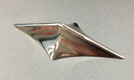
10 | Wheel pin (Cat’s eye) condition | O | O | O | O | 3 mo. | ||
11 | Center cap condition (Crack, distortion) | O | O | O | O | 3 mo. | 36 mo. | |
12 | Wheel level | O | O | 3 mo. | ||||
13 | Ept Sealer of the canter cap | O | O | O | 6 mo. | 12 mo. | ||
14 | Sensor hole condition | O | O | 6 mo. | ||||
15 | Clearance between bank and pocket | O | O | 6 mo. | ||||
16 | Gap between bank and pocket | O | O | 6 mo. | ||||
17 | Dead rebound position | O | O | 6 mo. | ||||
18 | Roller Assy and motor (Wheel) | O | 6 mo. | 24 mo. | ||||
19 | Fiber sensors condition | O | 6 mo. | |||||
20 | Projector filter condition | O | O | 6 mo. | 12 mo. | |||
21 | Tracking ball condition | O | 6 mo. | |||||
22 | Compressor filter condition | O | O | 6 mo. | 6 mo. | |||
23 | Separator filter(corner) condition | O | 6 mo. | 12 mo. | ||||
24 | Air pressure and ball rotation | O | O | 6 mo. | ||||
25 | Air regulator condition | O | 6 mo. | 24 mo. | ||||
26 | Air tube condition | O | 6 mo. | 36 mo. | ||||
27 | Air nozzle condition | O | 6 mo. | 36 mo. | ||||
28 | Electric air sensor condition | O | 12 mo. | |||||
29 | Projector (Placement/angle of image, focus) | O | 6 mo. | 24 mo. | ||||
30 | Projector setting before shipment | – | ||||||
31 | Live camera image (Focus, blurb brightness) | O | 6 mo. | |||||
32 | Perform I/O test | O | 6 mo. | |||||
33 | Confirm error meter | O | O | 6 mo. | ||||
34 | RNG test (10000games) | O | – | |||||
35 | Wheel unit (Repair) | – | 36 mo. | |||||
Must do the following acceptance inspection for the machines that arrived at the sales office.
Casino cannot operate that machine unless this machine passes all the test by using CHECK LIST on page 4.
NOTICE
Wheel units require repair once every three years due to aging of each part.
Check every 1 week depending on usage environment.
Open the Drain Spacer Door (between Station #6 and #7) and dispose of the drainage water.
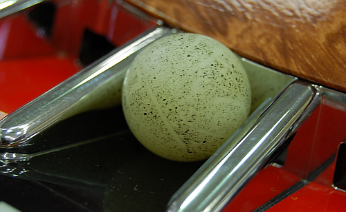
The ball has to be changed once every 3 months.
Check the surface of the ball with or without scars, stains and change of shape.
Change 90 degrees (9 pockets clockwise) every 3 months.
CAUTION
When executing pocket shuffle, please make sure that it is not visible from the player.
Also,
Be sure to leave a record of pocket shuffle.
AIso,
Keep the record in a place where you cannot see except the administrator.
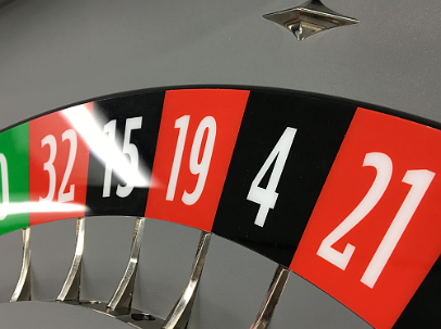
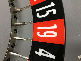
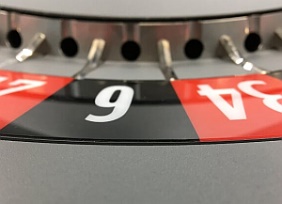
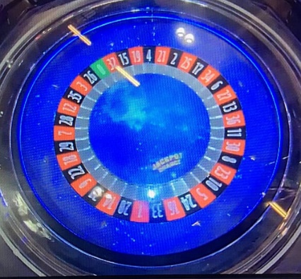
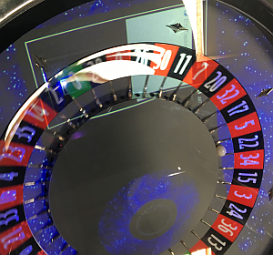
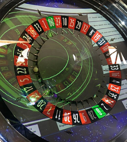
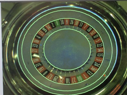
Traditional wheels could not change the positional relationship between pocket and number part, but with this machine it became possible and we could expect balanced game results over the long term.
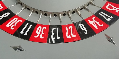
Number area
Pocket area
Specifically, the relationship that the following
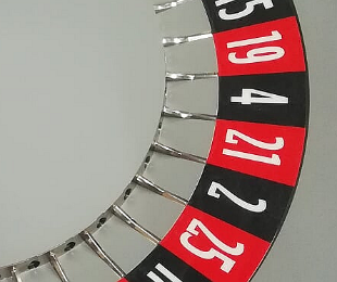
[Pocket # 1] = [0]
Pocket # | #1 | #2 | #3 | #4 | #5 | #6 | #7 |
Number | 0 | 32 | 15 | 19 | 4 | 21 | 2 |
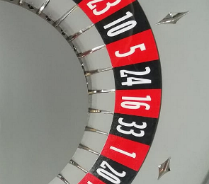
[Pocket # 1] can change to the relationship [32].
Pocket # | #1 | #2 | #3 | #4 | #5 | #6 | #7 |
Number | 32 | 15 | 19 | 4 | 21 | 2 | 25 |
Pockets can be moved anywhere in the 37 (38) number.
- Since the pocket and the number part are not fixed with screws etc., you can work just by removing the field glass.
- Mark both the pocket in the zero position and the destination number with tape or the like.
- Rotate the pocket wall with your finger while pressing the number part, and move it to the place where you marked the pocket. Each number position has a click feeling.
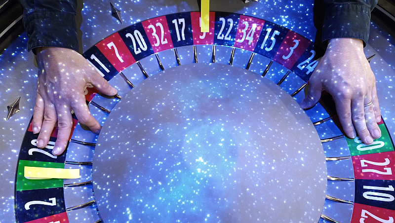
No need for setting. Software will be auto detected the pocket position.
Clean every 3 months.
Remove the accumulated dust as much as possible. Dust is removed in the same way in each box.
Check and Clean every day.
Clean the field glass and projector glass with clean and soft cloth.
Check and clean every 3 months, and has to be replaced every 36 months when the wheel unit repaired.
Check that there is no stain, scratch, air bubble, peeling, etc.
Bank
Check and clean every 3 months, and has to be replaced every 36 months when the wheel unit repaired.
Check that there is no stain, scratch, air bubble, peeling, distortion, gap, misaligned, etc.
Number sheet
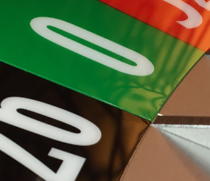
Gap
Distortion
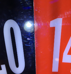
Check and clean every 3 months, and has to be replaced every 36 months when the wheel unit repaired.
Check that there is no stain, scratch, air bubble, peeling, distortion, misaligned, etc.
Replacement is recommended when there is peeling on the sticker.
Pocket sheet


Corner Peeling
Check every 3 months.
Check that it is fixed by using your finger.
Pocket wall
Ball pocket
Check every 3 months.
Check that it is fixed by using your finger.
Check every 3 months, and has to be replaced every 36 months when the wheel unit repaired.
Check that there is no stain, scratch, air bubble, peeling, distortion, misaligned, Gap, etc.
Center cap
Uniform Gap
NOTICE
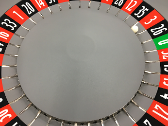
Carefully adjust every 3 months.
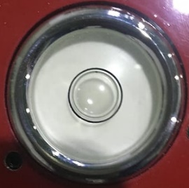
Check that the wheel is a true horizontal level by using a specific level gauge.
Check the level at three points every 60 degrees based on the ball’s launch (Home) position.
Adjust with the adjuster so that the bubble is perfectly centered at all measurement positions.
Ball starting position
Bubble must be perfectly center of the circle for all three position of the leveler.
<How to check the wheel level>
Make adjustments so that they are completely horizontal at all positions.
After adjusting the three position’s level, be sure to return to the Home Position again to check the level.
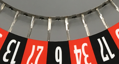
Check every 6 months, and has to be replaced every 12 months when the wheel unit repaired.
Check that there is no peeling, crushed, misaligned, etc.
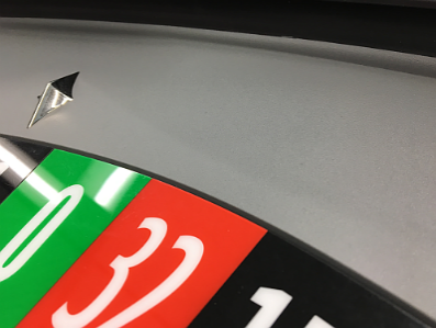
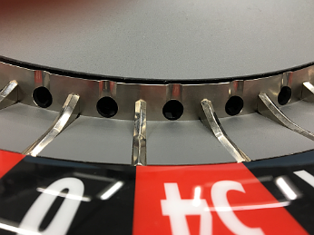
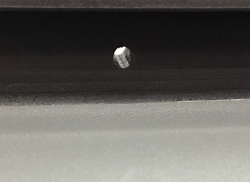
Check every 6 months.
Check that disturbance to ball running.
(In the photo, the sensor is off for explanation)
Sensor hole
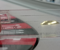
Check every 6 months.
Check that uniform clearance.
Uniform Gap
1.5 – 2.0mm
Check every 6 months.
Check that uniform clearance. Do not stop the ball here.
Uniform Gap
0.5mm
Gap
0 – +0.5 mm
WHEEL
Assy
BANK
Assy
1.5~2 mm
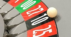
Check every 6 months.
Check the ball rebound on follows.
Drop the ball from all the pockets to a certain height and check the bouncing condition.
If the ball bounces up to the center cap, it is passed, and it is rejected if the ball only bounces in the pocket.

Drop the ball from all the number to a certain height and check the bouncing condition.
If the ball bounces up to the center cap, it is passed, and it is rejected if the ball only bounces in the pocket.
Drop the ball from between cats (7 positions) to a certain height and check the bouncing condition.
If the ball bounces up to the center cap, it is passed, and it is rejected if the ball only bounces in the pocket.
Check every 6 months, and has to be replaced to new one every 36 months.
Check if smoothly rotates and no strange noise.
Check every 6 months.
Check the following 6 fiber sensor functions by ROULETTE UNIT TEST.
Sensor Name | Connector |
POSITION SENSOR2(REF0130) (Pocket sensor I0130) | CN I0130 |
POSITION SENSOR3(REF0430) (Pocket sensor I0430) | CN I0430 |
POSITION SENSOR1(REF0730) (Pocket sensor I0730) | CN I0730 |
POSITION SENSOR4(REF1030) (Pocket sensor I1030) | CN I1030 |
Sensor Name | Connector |
AROUND SENSOR 1 (Wheel around sensor O1200) | CN O1200 |
AROUND SENSOR 2 (Wheel around sensor O0600) | CN O0600 |
Check the following 4 photo sensor functions by ROULETTE UNIT TEST.
Sensor Name | Connector |
Zero sensor | CN ENC |
Pocket Position 1 | CN ENC |
Pocket Position 2 | CN ENC |
Initial sensor | CN ZERO |

Position 1
Position 2

Zero
Initial
Check every 6 months, and has to be replaced to new one every 12 months.
WARNING
Since the projector’s light source uses a laser, please never disassemble the projector. There is a danger such as blindness.
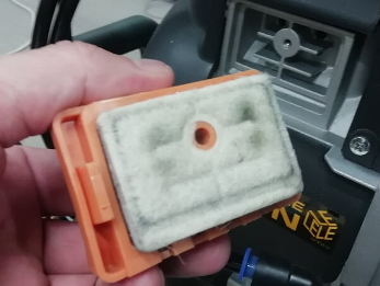
<Checking, cleaning, exchanging procedure>
- Slide the air filter covers lightly to the rear while holding the lock button to remove the air filter cover.
- Pull out the air filter cartridge straight by the grab of the air filter unit while pushing out one tab at a time on both sides.
- Remove the four air filter cartridges (two in each air filter unit) from the air filter unit sand clean the air filter with a vacuum cleaner.
When attaching the air filter cartridge to the cartridge holder, push the air filter cartridge in fully until the tabs of the cartridge holder click (4 points each air filter cartridge, a total of 8 points).
The two air filter units are installed in the right and left positions. - Return the air filter units to the projector.
The top and bottom of the air filter unit have different shapes, as illustrated below. Be careful of orientation when installing them.Slide the air filter unit in fully until the tabs on the projector click to hold it in place (2 points each air filter unit, a total of 4 points).
Close the air filter cover.
Check every 6 months.
Refer to tracking setting here
- Switch the tracking ball setting screen.

F10
+
♢
Press to tracking ball
- The tracking state during ball rotation is displayed as shown below.
If the software recognizes the ball, + will be displayed according to the movement of the ball.

+
Recognition of the ball is usually done immediately after shooting ball until the ball leaves the outer circumference.
If there is something wrong, + will jump or recognition time will be short.
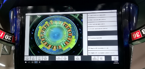
- If tracking does not work check the following points.
- Is the mounting position of the camera itself as shown in the picture?
- Whether the brightness level is around 40
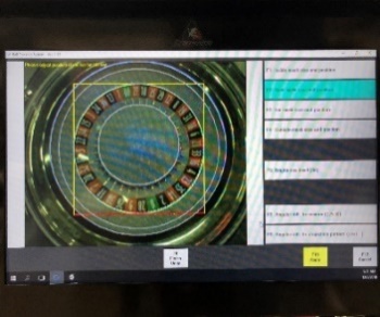

- Is the setting of 3 and 4 correct?

1.Inside Mask
2.Near Mask
3.Far Mask
4.Outside Mask
- Check that strong light and moving light are not reflected in the camera image.
NOTICE
Compressor units require replace once every 5 years due to aging of each part.
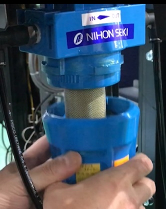
Check every 3 months, and has to be replaced to new filter every 6 months.
Check every 6 months and has to be replaced to new filter every 12 months.
Wash without detergent if the stain is found at 6 month checkout. Dry it well and restore. Replace if the stain cannot be come off.
NOTICE
Carefully inspect every 6 months
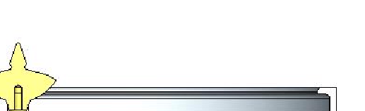
- Check the ball rise
NOTICE
Be careful when setting it as it will cause a ball shoot error
Select TEST>WHEEL UNIT TEST>AUTO RUN (RIGHT, CCW). The cycle of Ball Shooting and Rotation will repeat.
- Select MAIN>TEST>ROULETTE UNIT TEST>AUTO RUN
The cycle of Ball Shooting and Rotation will repeat.
- When the ball is blown up, visually check where it will land.
- Air adjustment is required in the following situations:
- The ball does not reach within 3mm of the outer wall of the wheel (see below).


0 – 3mm
×
Higher the RAISE pressure
- The ball’s trajectory is curving left or right before reaching the outer wall (see right).
Higher the RAISE pressure
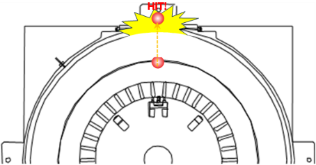
b) The ball’s trajectory is hitting the outside wall (see right).
Lower the RAISE pressure
Adjust the RAISE regulator(Left) to a point that is 0 – 3mm before the rim of the wheel.
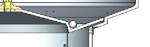
0 – 3mm
- How to adjust the RAISE air pressure
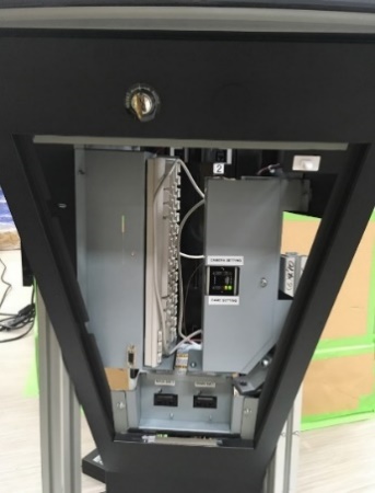
- Turn on the generator.
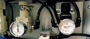
- Open #2 door of the generator. (Back of #2 playstation)
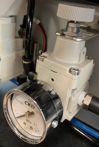
- There are two regulators inside the generator.
The air used to lift the ball is adjusted with the RAISE regulator on the left.
RAISE regulator
ROTATE regulator (DO NOT CHANGE)
Adjustment knob

Select TEST>ROULETTE UNIT TEST>AUTO RUN
The cycle of Ball Shooting and Rotation will repeat.
Locknut
- Loosen the locknut shown below.
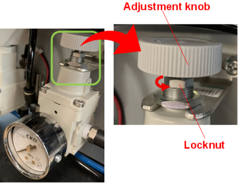
- Repeat the following steps until the ball reaches the correct position:
*It is okay to exceed the specified air pressure range (0.07~0.12Mpa).
<Higher the RAISE pressure> <Lower the RAISE pressure>

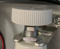
- Once the ball is in the correct position, tighten the locknut.
- Air adjustment is complete.
- How to adjust the ROTATE air pressure
The time from the ball being released to the WIN number being confirmed is adjusted to be around 27 seconds.
Check every 6 months and has to be replaced to new regulator every 24 months.
NOTICE
If the regulator has failed, a ball shoot error such as BALL START ERROR will occur.
Check the movement of the regulator needle during the game operation.
- Needle movement is jerky and not smooth
- Needle movement is slow and does not follow changes in pressure
Check every 6 months and has to be replaced to new tube every 36 months.
Check if air leak, pinch, crack, and deterioration of the tube and joint part.
Check every 6 months and has to be replaced to new nozzle every 36 months.
Check if cracks, clogging due to accumulation of impurities.
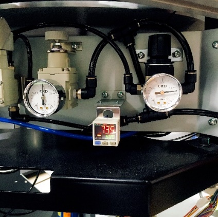
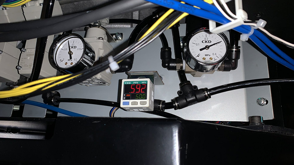
Check every 12 months
Check if the value displayed in “Electric air sensor” is normal.
Press the SET button to alternately display “P-1” and the set value.
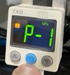
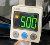
Displayed value = .500
NOTICE
The electric air sensor is factory set to the proper value and should not be changed.
Changing the settings of this device will cause COMPRESSOR ERROR.
Click here for initialization procedure
Check every 6 months and has to be replaced to new regulator every 24 months.
Check if the image will be blurry, whitish, or dim.
Watch the live camera image of the station or main signage and check the image delay, deviation of shooting range, color, and focus.
If you replaced the camera, follow the steps below to make settings on the camera side.
- One main unit to which the camera (w/lens) is to be installed.
- One station.
- One Windows PC that installed “Easy Config for FB-H200Np” (Download here(Official page))
- Two LAN cables (cat 5e or above)
- Ethernet hub
- Mass produced SSD (Main and Station)
NOTICE
IP address for PC to be used should be “Automated IP address acquisition”, “IP address [192 168 201 1]” and “subnet mask [255 255 255 0]”.
- Attach the camera to the main unit and connect the LAN cable and power connector.
- Connect LAN cable PC to Main unit HUB.
- Boot up the main unit and PC.
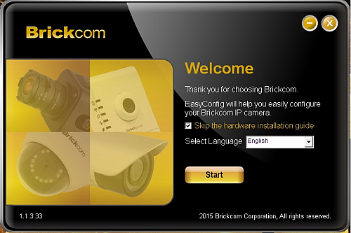
- Startup Easy Config application on the PC.
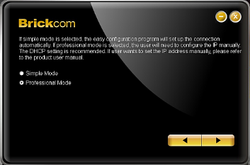
- Click Start button, then select “Simple mode” and right arrow
- If the camera connected is shown like as below, select row No.1 and click the right arrow.
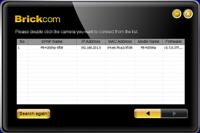
- Click “Live view” to go to the configuration of the camera main body.
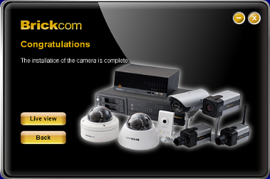
- Enter “admin” into the entry boxes if needed.
- The screen is displayed like as follows if the plug-in has normally been installed and live mages can be seen.
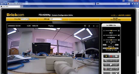
- Change the language with the Language button as necessary.
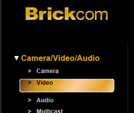
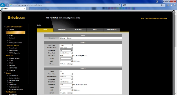
- Click “Configuration” displayed on the upper right of the screen below and then, click “Video” that is a sub item for “▽Camera/Video/Audio”.
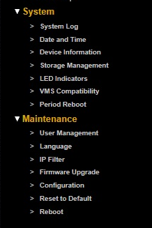
- Click the “Configuration” tab and scroll down the window. Click “Maintenance” and “Configuration”
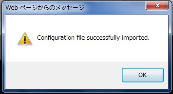
- Select the configuration file “H200Np_LRX_2019-01-31.cfg” by Browse button, and click “Import” button.
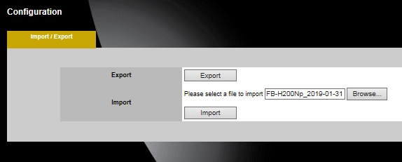
Continue to the next page
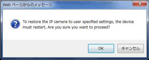
Click “OK”
- Close EasyConfig by X button.

- Restart EasyConfig.
- Click “Configuration” displayed on the upper right of the screen below and then, click “Video” that is a sub item for “Camera/Video/Audio”.
Confirm that the screen below is displayed. Click the “Stream” tab and check the information contained in the red box below into the items for “Stream 1”.
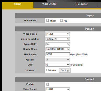
Video Codec: H.264
Video Resolution: 1280×720
Frame Rate: 60
Bitrate Mode: Constant Bitrate
Max Bitrate: 5000
Quality: 3
GOP: 0
i-Stream: Enable
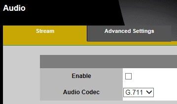
- Click “Audio” that is a sub item for “Camera/Video/Audio”.
Check the appropriate information into the items for “Stream” as the following screen shows.
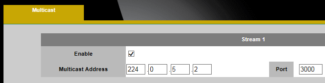
- Click “Multicast” that is a sub item for “Camera/Video/Audio”.
Check the appropriate information into the items for “Stream 1” as the following screen shows.
- Click “Network Settings” that is a sub item for “Network”. Check the appropriate information the items as the following screen shows.
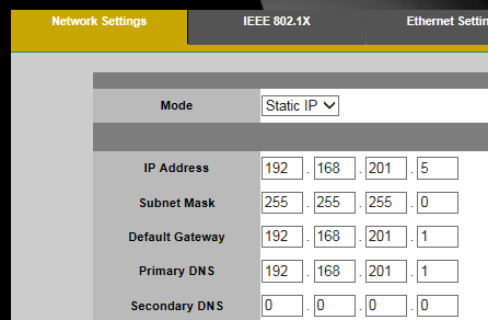
Mode: Static IP
IP address: 192.168.201.5
Subnet mask: 255.255.255.0
Default Gateway: 192.168.201.1
Primary DNS: 192.168.201.1
Secondary DNS: Blank
- Click “Camera” that is a sub item for “Camera/Video/Audit”. And click “Import Setting”.

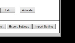
- Click “Browse… and select the file “H200Np_LRX_FS_50Hz_20190214” or “H200Np_LRX_FS_60Hz_20190214”.
and click “Import”.
* [Power Supply Frequency]: Select 50Hz or 60Hz in this screen according to the commercial frequency employed in the jurisdiction.
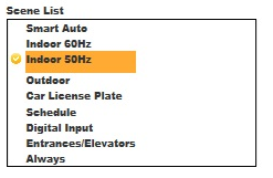
- Appear new scene at bottom part of Scene List.
If selected file is “H200Np_LRX_FS_50Hz_20190214”, appear “factory setting 50Hz”. And if selected file is “H200Np_LRX_FS_60Hz_20190214”, appear “factory setting 60Hz”.
Select the new scene and then click “Active”.
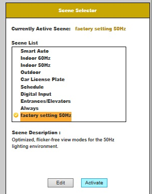
- Click “Edit” and check the values in the items for “Scene Setting” as the following image shows.

- Click “Day Profile”.
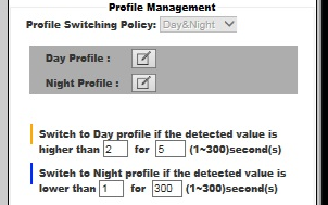
- Confirm that the “Profile Setting” screen is displayed. Check the appropriate information into the items below.
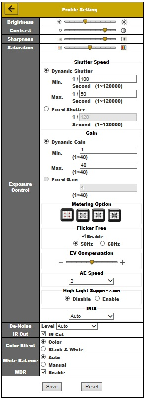
*Caution
The screen flickers if 50 Hz is selected because the power supply frequency employed in Philippine is 60Hz.
Even if the screen flickers during production, do set the power supply frequency used in the destination.
- Click “x” to close the browser window.
- Click “x” or “Exit” to close all windows for “EasyConfig”.
- Unplug all cables and turn off the PC.
- This concludes the configuration.
Chi-square (Random Number) test
This is a statistical method to check whether the distribution can be regarded as almost the same as the theoretical value distribution.
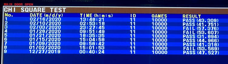
This machine performs the test based on the game results of 10,000 shots and saves the test results of the past 10 times in AUDIT.
The chi-square criterion is indicated at the confidence level, and 95% or 99% is usually used.
95% means that 5% is not the correct distribution, but the remaining 95% is the correct distribution, so this distribution is almost correct.
Although the standard value differs depending on the regulations of the region, etc., Aruze’s standard uses the strictest standard.
GLI | NEVADA/ NEW MEXICO | Aruze Standard | |
Confidence | 99% | 95% | 95% |
Chi square limit value | S0: 58.62 D0: 59.89 | S0:51.00 D0:52.19 | |
Evaluation outcome | 10,000 | 10,000 | 10,000 |
Must save 10 chisquared history | No | Yes | Saved 20 results |
Default setting of self chisquared test | Disable | Enable | Depending on GAL |
Equal distribution test | Yes | Yes | Yes |
Gap test | No | No | Yes (Only performed before installation) |
This machine has a function to perform chi-square test by itself.
Every 10,000 games are evaluated based on the 95% confidence level, and the results of the last 20 games are stored in AUDIT.
<AUDIT structure>
MAIN AUDIT > RECALL METER > CHI SQUARE TEST
The self chi-square setting can be selected from 4 options below.
Settable in [MAIN > SETTING > MAIN UNIT SETTING > CHI SQUARE]
- DISABLE:
Do not run the internal chi-square test. - TEST ENABLED TYPE 1:
Run the internal chi-square test. In case of failure, lock up every 10,000 games. - TEST ENABLED TYPE 2:
Run the internal chi-square test.
Display “WHEEL MAINTENANCE REQUIRED” message when test continuously failed for 2 times - TEST ENABLED TYPE 3:
Run the internal chi-square test.
Display “CALL ARUZE SERVICE” message when test continuously failed for 2 times. In second lockup, need to input password for reset (cannot reset by reset key).
Password: reve4xam * This password is a common password that does not change. |
<Setting condition>
Setting Name | Self chi-square | 1st fail | 2nd fail | Stored game result | Record 20 chi-square result |
DISABLE | Disable | No lockup | No lockup | 100k game result in Backup SSD | Yes |
TEST ENABLED | Enable | “SELF CHI SQUARE TEST FAILURE” | — | ||
TEST ENABLED | Enable | “SELF CHI SQUARE TEST FAILURE” | “WHEEL MAINTENANCE REQUIRED” | ||
TEST ENABLED | Enable | “SELF CHI SQUARE TEST FAILURE” | “WHEEL MAINTENANCE REQUIRED CALL ARUZE SERVICE” |
The characteristic of the chi-square test is that it is a test that saw the moment of the 10,000th game.
Therefore,
If the result of FAIL is given when the chi-square value is about + 20% of the upper limit, it should be judged that there is no abnormality.
Limit of chi square value | Tolerance (+20%) | |
Single Zero | 51.00 | 61.20 |
Double Zero | 52.19 | 62.63 |
The 20 test results recorded in AUDIT are judged as follows.
Is FAIL% of all results over 30%?
Yes
No
Is Total RTP over 100%?
No problem
Perform
NOTICE
NEVER install the machine to venue unless you pass this test.
The RNG test is also called chi-square test.
This is a random number inspection for the wheel. The RNG test includes a chi-square test that examines the distribution of WIN and a GAP test that examines the distribution of differences between two consecutive WINs.
RNG tests and their data collection require WINDOWS PC, Ethernet cable and special windows application (LuckyRouletteChiSquare.exe).
Ethernet HUB
Main PCB
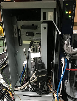

LuckyRouletteChiSquare.exe
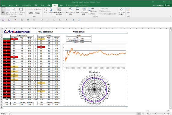
Open the csv file in the chi-square application folder. And copy all data of D to E cells.
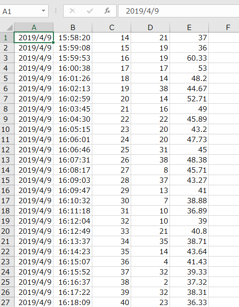
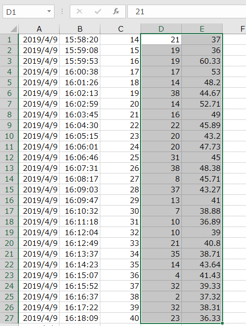
CSV file
CSV file
Paste to chi-square format.
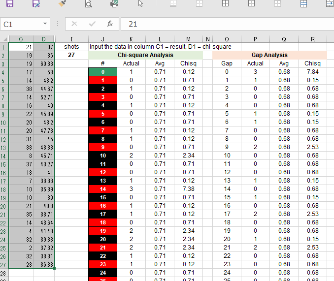
Test results are automatically calculated on sheet [Basic Test] in chi-square format.
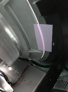
NOTICE
The camera used for tracking the ball is affected by lighting environments, so it be sure to set at the installation location.
If there are following reflect on the wheel glass in the tracking camera image, ball tracking may not operate properly.
a. Strong light
b. Moving light
c. Ambient is too bright or dark (200 to 300 lx is the best).
If unavoidable external light is reflected, change the angle of lighting or the installation angle of the machine.
it’s bad for tracking ball
It’s the projector’s own light source, It is no problem.
After booting up the main unit, check the reflection of external light by following operation.
- The display switcher to “TRACKING CAMERA SCREEN” by pressing the button that in the main corner.

- Immediately after booting up, BallTracking is minimized on the projector display.
- [ALT]+[TAB], to focus to BallTracking appli.
When BallTracking is focused, release [TAB]. - [Windows]+[SHIFT]+[→] to move the appli onto the signage LCD.
- [Windows]+[Shift]+[↑] to maximize the window.
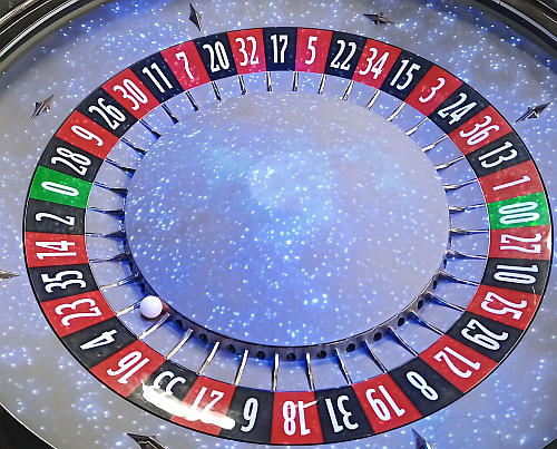
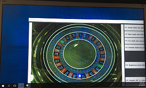
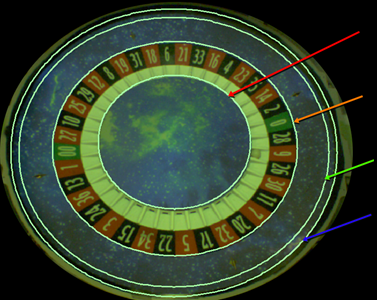
In this step, set the tracking range of the ball by aligning the four circles with the wheel image.

Four circles as follows;
1.Inside Mask
2.Near Mask
3.Far Mask
4.Outside Mask
Circle | Description |
| This should be positioned inside the pocket section and at the circumference of the center cap. |
| This should be positioned outside of the number area. |
| This should be positioned at the inner side of the ball passing the most outer circumference. Before adjusting Far Mask, make an adjustment of Outside Mask. |
| This should be positioned at the inside of the bank and the edge of the black roof. This setting should be performed accurately. |
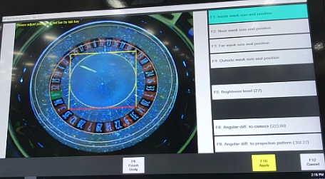
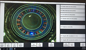
<Key assign for setting screen>
Keyboard | Function |
[♢] + [1] | Select “Inside Mask” |
[♢] + [2] | Select “Near Mask” |
[♢] + [3] | Select “Far Mask” |
[♢] + [4] | Select “Outside Mask” |
[♢] + [5] | Adjusting brightness |
[♢] + [8] | Adjusting camera angle |
[♢] + [8] | Adjusting projector angle |
⇦⇨⇧⇩ | Adjust the circle |
[Tab] | Select the adjustment place of circle |
[♢] + [10] | Exit one of the Mask setting |
In this chapter a content in “[ ]” means a key on the keyboard.
“+” is used for describing that 2 or more keys are simultaneously pressed.
1. Projector display
2. Projector controller PC
3. Lucky Roulette Main unit
- The display switcher to “TRACKING CAMERA SCREEN” by pressing the button that in the main corner.

- Immediately after booting up, BallTracking is minimized on the projector display.
- [ALT]+[TAB], to focus to BallTracking appli.
When BallTracking is focused, release [TAB]. - [Windows]+[SHIFT]+[→] to move the appli onto the signage LCD.
- [Windows]+[Shift]+[↑] to maximize the window.

- Remove the camera cover by two screws.
- Loosen the 4 screws as below, then the camera becomes movable.
- fit the top of the wheel edge with the top of the screen.

- Adjust the focus by focus ring.
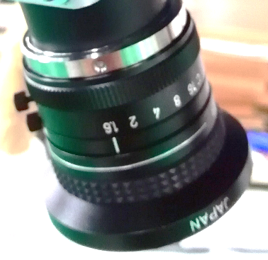
Focus ring
- Fix the 4 screws, and return the camera cover
<Image of setting order>
You can pay attention where 3 and 4 are replaced.
Continue to the next section
- Make the following state according to the procedure of “<Preparing>“

- Press [♢] + [1] by keyboard to display the Inside Mask circle.
- Move the side of the red line with the cursor key and align it to the outer periphery of the center cap.
The original line is indicated by a dotted line.
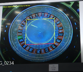


- When one side is adjusted, pressing the [TAB] moves the red line. And align it to the outer periphery of the center cap.

- Similarly adjust the four sides and press [♢] + [10] at the end.
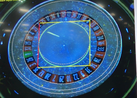
- Press [♢] + [2] to display the Near Mask circle.
- Adjust the four sides to the outside of the number area by the same procedure. And [♢] + [10] at the end.
- Press [♢] + [4] to display the Outside Mask circle.
- Adjust the four sides to the outside of the number area by the same procedure. And [♢] + [10] at the end.
- Press [♢] + [3] display the Outside Mask circle.
- Adjust the four sides to the outside of the number area by the same procedure. And [♢] + [10] at the end.
NOTICE
 The camera’s brightness setting is adjust the brightness on the camera side if it cannot be set to the specified value in the setting on the application side.
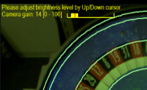
Press [♢] + [5] to display the brightness setting screen.- Adjust with the up and down keys of the cursor so that the average of the numbers in the red circle in the figure will be about 40.


- Press [♢] + [10] at the end
Continue to the next section
NOTICE
225.00 is entered as an initial value.
Change it when the ball rotation effect is deviated.
- Press [♢] + [8] to display the camera angle setting screen.
- Adjust the angle with the keys in the table below.
- Press [♢] + [10] at the end
Continue to the next section
<Keyboard assign>
Key | Function |
[↑] | Increase angle by 1 degree. |
[↓] | Decrease angle by 1 degree. |
[Shift] + [↑] | Increase angle by 0.1 degree. |
[Shift] + [↓] | Decrease angle by 0.1 degree. |
[Ctrl] + [↑] | Increase angle by 0.01 degree. |
[Ctrl] + [↓] | Decrease angle by 0.01 degree. |
[♢] + [10] | Apply changing and exit Angular diff. to camera mode |
[♢] + [12] | Cancel and exit Angular diff. to camera mode |
NOTICE
0.50 is entered as an initial value. Please change it when the winning number or jackpot number lighting.
- Press [♢] + [9] to display the camera angle setting screen.
- Adjust the angle with the keys in the table below.
- Press [♢] + [10] at the end
Continue to the next section
<Keyboard assign>
Key | Function |
[↑] | Increase angle by 1 degree. |
[↓] | Decrease angle by 1 degree. |
[Shift] + [↑] | Increase angle by 0.1 degree. |
[Shift] + [↓] | Decrease angle by 0.1 degree. |
[Ctrl] + [↑] | Increase angle by 0.01 degree. |
[Ctrl] + [↓] | Decrease angle by 0.01 degree. |
[♢] + [10] | Apply changing and exit Angular diff. to camera mode |
[♢] + [12] | Cancel and exit Angular diff. to camera mode |
- When setting is completed, Press [♢] + [12] and next [Enter] to close application. (for saving setup data)
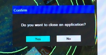
- Then press [Ctrl] + [Alt] + [Del] by the keyboard.
+
+
Alt
Ctrl
Del
- Select [Sign out] by the [Tab] key and then [Enter] to logging out.
At this time the output destination of the display automatically changes to the projector screen. - Press [Enter] when the WINDOWS screen appears (Log in), and then application is automatically executed.
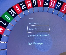
By Tab
Appear Log in screen
Enter
- Two images displayed on the projector screen (on wheel). No image on the signage screen at this time.
Alt
Tab
+
to focus on red window below
Tab
And remove your finger on
- Displayed tracking setting window on the projector screen (on the wheel)
to move the window of tracking setting screen to signage screen
♢
Shift
+
+
→
to maximize the tracking setting window on the signage LCD screen.
♢
+
↑↑

Press “TRACKING CAMERA SCREEN” by display switcher that in the main corner.
Continue to the next section
- Switch the tracking ball setting screen.

F10
+
♢
Press to tracking ball
- The tracking state during ball rotation is displayed as shown below.
If the software recognizes the ball, + will be displayed according to the movement of the ball.
+
Recognition of the ball is usually done immediately after shooting ball until the ball leaves the outer circumference.
If there is something wrong, + will jump or recognition time will be short.
- If tracking does not work check the following points.
- Is the mounting position of the camera itself as shown in the picture?

- Whether the brightness level is around 40


- Is the setting of 3 and 4 correct?
1.Inside Mask
2.Near Mask
3.Far Mask
4.Outside Mask
- Check that strong light and moving light are not reflected in the camera image.
Information for installation
Step 1
Connect projector plug
Step 2
Connect tracking PC plug
Step 3
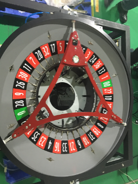
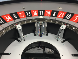
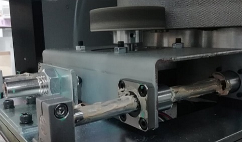
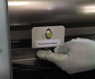
You have to remove the shipping before first installation (operation).
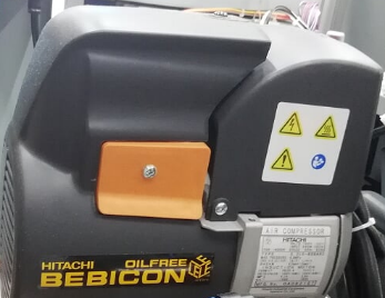
- Remove the wheel fixing tape. (Left photo)
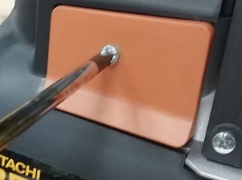
There is 3 or 4 fixing tape under the wheel. - Remove 2 compressor shipping bracket. (Right photo)
Turn the Focus Ring to adjust the focus.
Focus ring
- Adjusting the Position (Lens shift)
- Open Main Audit > SETTING > HARD WARE SETTING > LENS SHIFT
- Move the game image displayed on the roulette wheel to the center with the cursor keys on the keyboard.
1735
2735
2640
972
3050
NOTICE
Maximum number of stations can be 50p
(Base 8p + 42p)
This machine needs power outlets for the
Center Unit
exclusive power plugs for the Projector
the Tracking CAMERA PC
each Station
and the optional USB Chargers.
Pole4
+
Filter
Spacer
Pole3
Pole2
+
Control
Spacer
Pole1
FAN 4
FAN 3
Pole4
+
Filter
Spacer
Pole3
Pole1
FAN 1
FAN 2
Pole2
+
Control
Spacer
- An error occurs when the time to stop the wheel at the launch position exceeds 60 seconds.
- Check the following 3 photo sensor functions by ROULETTE UNIT TEST. It is also possible that the ball is too dirty.

- After the ball is launched, the winning number is fixed within 5 laps and an error occurs if it is continued three times.
- Air adjustment may be incorrect. Check the ball launch condition in the ROULETTE UNIT TEST.
- Check the following 2 fiber sensor functions by ROULETTE UNIT TEST.
Sensor Name | Connector |
AROUND SENSOR 1 (Wheel around sensor O1200) | CN O1200 |
AROUND SENSOR 2 (Wheel around sensor O0600) | CN O0600 |
- An error occurs if the winning number is not finalized within 60 seconds after the ball is launched.
- Check if the ball is in the wheel. It is also possible that the ball is too dirty.
- Check the following 4 fiber sensor functions by ROULETTE UNIT TEST.
Sensor Name | Connector |
POSITION SENSOR2(REF0130) (Pocket sensor I0130) | CN I0130 |
POSITION SENSOR3(REF0430) (Pocket sensor I0430) | CN I0430 |
POSITION SENSOR1(REF0730) (Pocket sensor I0730) | CN I0730 |
POSITION SENSOR4(REF1030) (Pocket sensor I1030) | CN I1030 |
- An error occurs when the compressor preparation (compression) time exceeds 30 seconds.
- Check the function of the compressor and pressure gauge.
- This error also appears even if the compressor valve is closed.
- It occurs when judging that there are two or more balls in a pocket.
- Check the following 4 fiber sensor functions by ROULETTE UNIT TEST.
Sensor Name | Connector |
POSITION SENSOR2(REF0130) (Pocket sensor I0130) | CN I0130 |
POSITION SENSOR3(REF0430) (Pocket sensor I0430) | CN I0430 |
POSITION SENSOR1(REF0730) (Pocket sensor I0730) | CN I0730 |
POSITION SENSOR4(REF1030) (Pocket sensor I1030) | CN I1030 |
- If the origin cannot be found even if the wheel circulates, and the encoder sensor does not change.
- There is a possibility that the wheels are not rotating even though the motor is rotating. In this case, check the periphery of the motor roller.
- Check the following 3 photo sensor functions by ROULETTE UNIT TEST.
Sensor Name | Connector |
Zero sensor | CN ENC |
Pocket Position 1 | CN ENC |
Pocket Position 2 | CN ENC |

- An error occurs if each sensor does not respond despite the rotation of the wheel, or if the state does not change for 3 seconds or more.
- Check the following 4 fibersensor functions by ROULETTE UNIT TEST.
Sensor Name | Connector |
POSITION SENSOR2(REF0130) (Pocket sensor I0130) | CN I0130 |
POSITION SENSOR3(REF0430) (Pocket sensor I0430) | CN I0430 |
POSITION SENSOR1(REF0730) (Pocket sensor I0730) | CN I0730 |
POSITION SENSOR4(REF1030) (Pocket sensor I1030) | CN I1030 |
- An error occurs if zero sensor does not respond despite the rotation of the wheel, or if the state does not change for 3 seconds or more.
- Check the zero sensor functions by ROULETTE UNIT TEST.

- An error occurs when the Zero sensor does not react even if the wheel rotates twice at the wheel initialization time.
- Check the zero sensor functions by ROULETTE UNIT TEST.

- An error occurs when two sensors react at the same time, or when one sensor reacts 15 times in a row.
- Check the 2 around sensor functions by ROULETTE UNIT TEST.
Sensor Name | Connector |
AROUND SENSOR 1 (Wheel around sensor O1200) | CN O1200 |
AROUND SENSOR 2 (Wheel around sensor O0600) | CN O0600 |
- An error occurs when the encoder count does not change although the motor is moving.
- Check the following 2 photo sensor functions by ROULETTE UNIT TEST.
Sensor Name | Connector |
Pocket Position 1 | CN ENC |
Pocket Position 2 | CN ENC |

- An error occurs when the pocket position at initialization differs from the pocket position at the game.
- Check the following 4 photo sensor functions by ROULETTE UNIT TEST.
Sensor Name | Connector |
Zero sensor | CN ENC |
Pocket Position 1 | CN ENC |
Pocket Position 2 | CN ENC |
Initial sensor | CN ZERO |
Position 1
Position 2
Zero
Initial
- An error occurs when the home sensor does not react even if the wheel rotates once.
- Check the following 4 photo sensor functions by ROULETTE UNIT TEST.
Sensor Name | Connector |
Zero sensor | CN ENC |

- When the stepping motor moves 20 pulses, an error occurs when rotating in the direction opposite to the direction of rotation instructed by software.
- Check all sensor and motor functions by ROULETTE UNIT TEST.
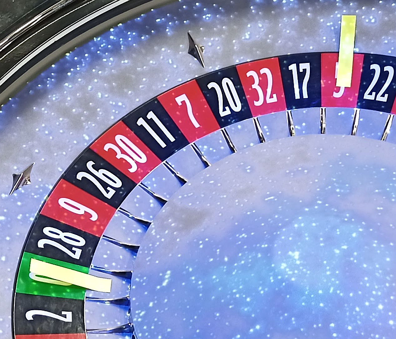
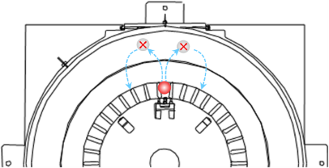
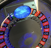
Three sensors (blue) constantly monitor the position of the wheel, and the four sensors (red) always monitor balls in their pockets.
When the red sensor first detects the ball, it judges the WIN number based on the blue sensor information.
At this point the machine still does not finalize WIN.
When the wheel rotates and the second red sensor detects the ball, the WIN determination is also made there.
And if the WIN number of the first sensor is the same as the second sensor (when the same number is judged in two consecutive) WIN is confirmed.
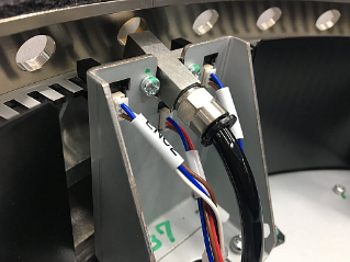
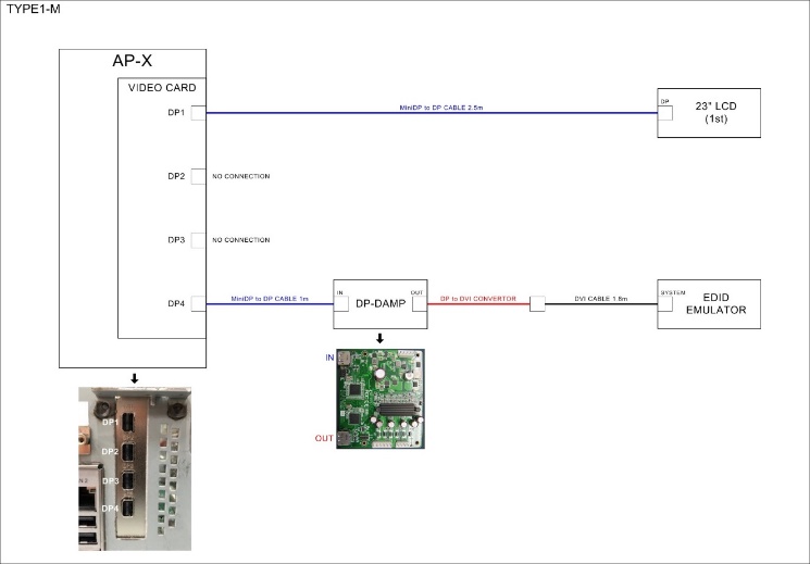
- Check the following connections. In particular, pay attention to the connection port of the Mini DP (Video card).
DP-DAMP connection port differs between main and station.
NOTICE
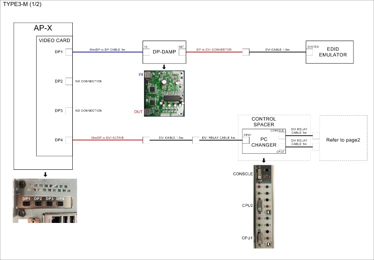
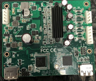
- Check the version of DP-DAMP
Only the DP-DAMP which does not have 0315 marking can be used in the lower right of the PCB.
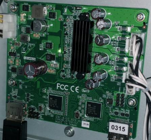
Check the following connections. In particular, pay attention to the connection port of the Mini DP (Video card).
DP-DAMP connection port differs between main and station.
NOTICE
Intentionally blank
This machine can output the signage and projector image externally.
Image output | Resolution | Splitting |
Signage image | 1920×1080 | The DVI splitter in signage |
Projector image | 1920×1200 | On the projector connection panel |
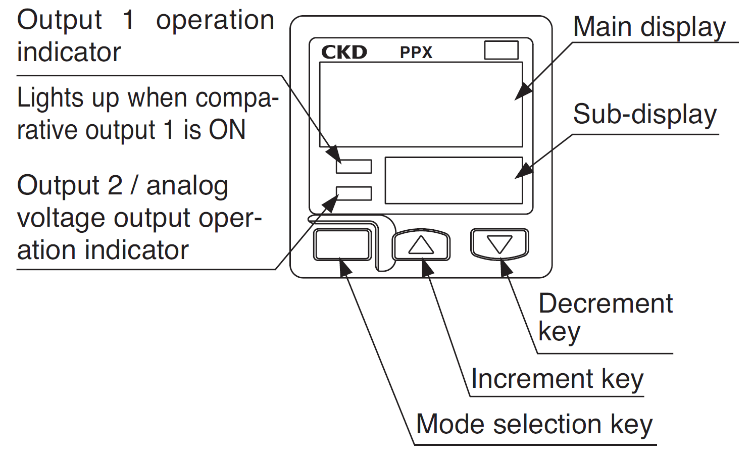
If the setting of ELECTRIC AIR SENSOR setting has been changed, initialize it by the following method.
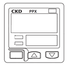
There are two types of ELECTRIC AIR SENSOR, PPG and PPX.
Electric air sensor
NOTICE
The electric air sensor is factory set to the proper value and should not be changed.
Changing the settings of this device will cause COMPRESSOR ERROR.
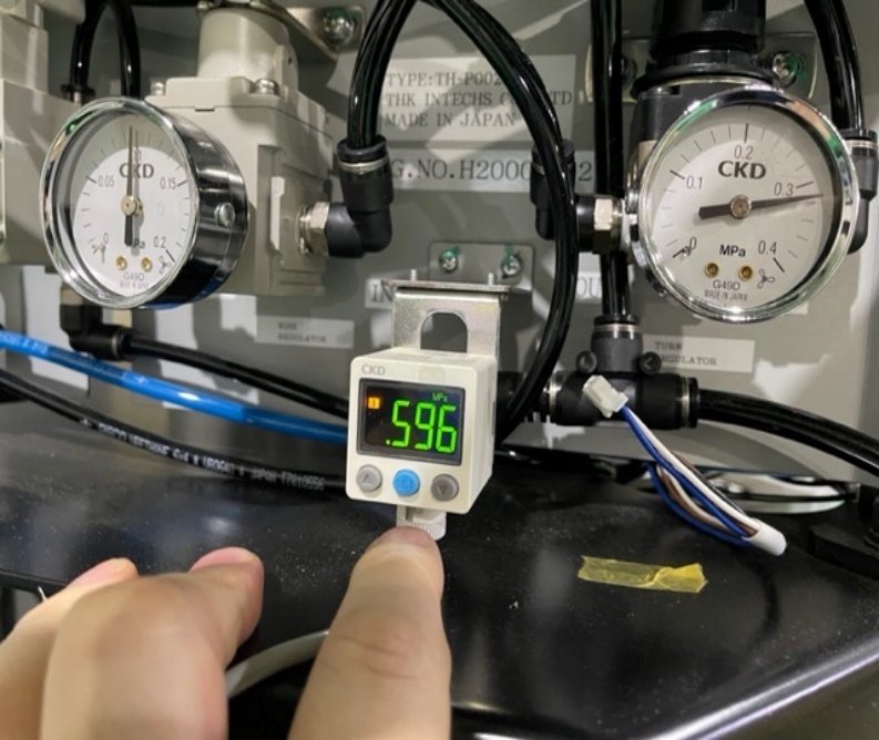
<Initializing (PPX type)>
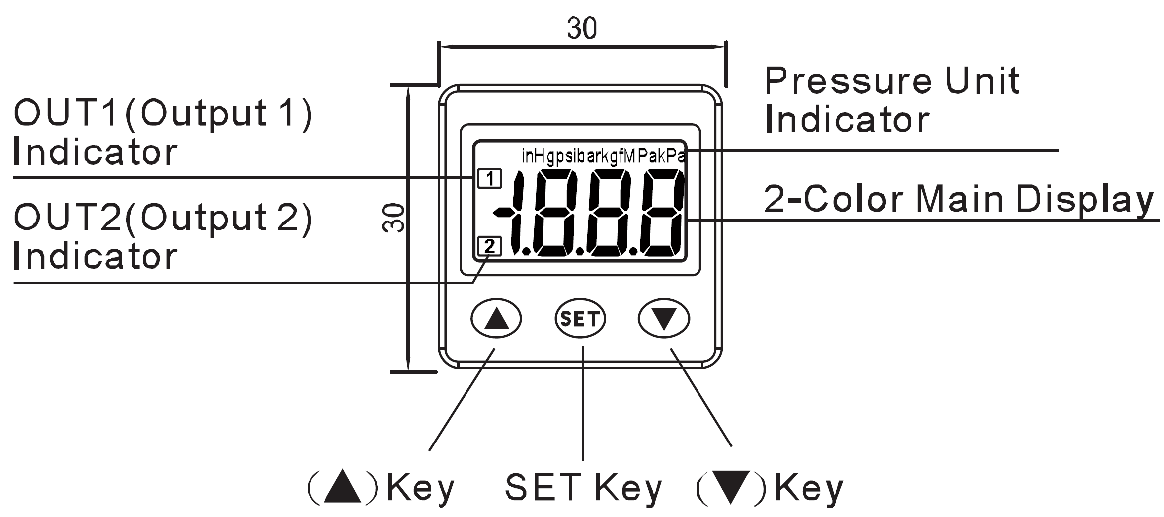
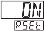
- Push and hold the SET button (about 5 seconds) until the display changes to “alternate display of rSt and oFF” (state shown in the photo below).
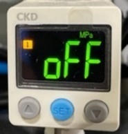

SET button
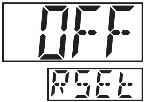
- Push the ↓ button to change to “on”.
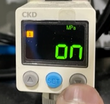
↓ button
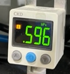
- Push the SET button to return to the operation mode.
There is no display indicating OPERATION mode. Operation mode is the mode in which the value fluctuates while the compressor is operating.
<Initializing (PPG type)>
- Push and hold the MODE selection key (about 5 seconds) until the display changes to “PRO MODE” (state shown in the photo below).

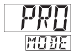
![]()
MODE selection key
- Push the MODE button several times until the following is displayed.


![]()
MODE button
- Push the ↓ button to change to “on”.
![]()
↓ button
- Push the MODE button to return to the operation mode.
There is no display indicating OPERATION mode. Operation mode is the mode in which the value fluctuates while the compressor is operating.
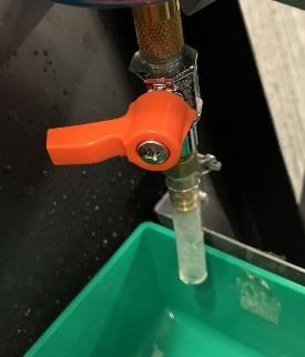
Water may accumulate inside the separator due to dirt on the filter.
Air is leaking from the tube at the bottom of the separator.
In this case:
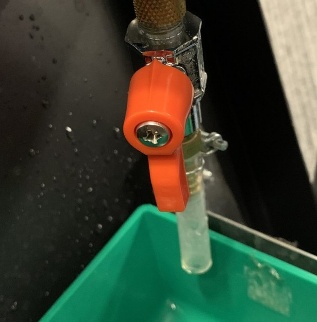
- Press the leaking end of the separator’s lower tube with your finger several times.
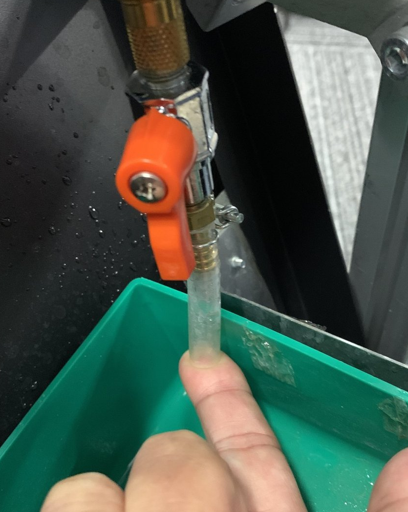
- Discard the water that has accumulated in the separator’s water tray.
Water will come out of the tube. When water stops coming out, return the cock to its original position.
Original position Water discharge
If the air leak is not resolved after these two measures, the separator will need to be replaced.
In rare cases, the images on the TOP LCD and the projector may be switched when the main unit is booted up.
This happens when the video equipment information is inaccurate, so replace the video cable if this symptom persists.
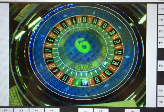
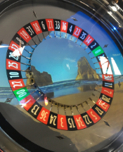
In this case, the image of the “galaxy image” that should normally be projected on the wheel is displayed on the TOP LCD, and projector displays WINDOWS screen.

- If the Top LCD displays the game image, press the “TRACKING CAMERA SCREEN” where in the main corner to change to the track ball setting screen.
- to focus on the “Galaxy image”.
Tab
Alt
+
- And remove your finger on
Tab

(or ) to move the window of galaxy image to the projector screen (switched screen image).
♢
Shift
+
+
→
←
- Galaxy image displayed on the projector screen.
- If the galaxy window was too small, to maximize window.
♢
+
↑↑
ITEM | Options |
WHEEL SPEED | Displays the speed of the wheel motion. |
WHEEL BLOW UP | Set how long the air valve for ball rising will be activated. |
WHEEL AROUND | Set how long the air valve for ball rotation will be activated. |
WHEEL DIR | Set if the wheel will spin clockwise (CW) or counter clockwise (CCW) |
BALL DIR | Set if the ball will spin clockwise (CW) or counter clockwise (CCW) |
WHEEL DELAY | Set the time between the air jet blowing the ball upward and the air jet blowing the ball for rotation. |
CMD DATA INITIALIZE | The data are initialized. |
MOTOR RUN | The wheel starts to spin. |
ALL STOP | Stops all the test operations. |
MOTOR STOP ON VALVE | Stops the ball on the air valve. |
AUTO RUN | The wheel routine motion during game is carried out for test purpose. |
VALVE TEST MODE UP | The air valve for ball rising is activated. |
VALVE TEST MODE CW | The air valve for ball turning clockwise is activated. |
VALVE TEST MODE CCW | The air valve for ball turning counter clockwise is activated. |
VALVE STOP | The air valve is stopped. |
ITEM | Options |
HIT NUMBER | The number of the pocket where the ball lays, is displayed. |
BALL AROUND NUMBER | The number of turns run by the ball is displayed. |
WHEEL AROUND NUMBER | The number of rotations of the wheel is displayed. |
COMPRESSOR PRESSURE | The status of the compressor is displayed. |
SENSOR1 (REF0130) HIT NUMBER – SENSOR2 (REF0430) HIT NUMBER – | When the ball position is identified by the Sensors 1 to 4, the correspondent wheel pocket number is displayed. |
SENSOR3 (REF0730) HIT NUMBER – | |
SENSOR4 (REF1030) HIT NUMBER – | |
SENSOR1 (REF0130) BALL COUNT – | The number of balls identified by the Sensor 1-4 is displayed. |
SENSOR2 (REF0430) BALL COUNT – | |
SENSOR3 (REF0730) BALL COUNT – | |
SENSOR4 (REF1030) BALL COUNT – | |
WHEEL TYPE | The wheel type is displayed. |
POKET SHUFFLE(INIT) | The pocket shuffle initial value is displayed. |
POKET SHUFFLE (NORMAL) | The pocket shuffle normal value is displayed. |
WHEEL ENCODER COUNT | The counter of the wheel encoder is displayed. |
WHEEL LAST ENCODER COUNT | The counter of the wheel last encoder is displayed. |
BALL COUNT | The number of balls is displayed. |
ITEM | Options |
POSITION SENSOR ERROR (REF0130) – | The status of each Position Sensor is displayed. |
(REF0430) – | |
(REF0730) – | |
(REF1030) – | |
ZERO SENSOR ERROR | The status of the Zero Sensor is displayed. |
ZERO SENSOR DETECT ERROR | The status of the Zero position identification is displayed. |
AROUND SENSOR ERROR | The status of the Around Sensor is displayed. |
ENCODER COUNT ERROR | The status of the Encoder Count is displayed. |
MOTOR ERROR | The status of the Motor is displayed. |
POKET SHUFFLE ERROR | The status of the Pocket Shuffle is displayed. |
WHEEL ORIGIN DETECT ERROR | The status of the Origin position identification is displayed. |
WHEEL DIRECTION ERROR | The status of the Wheel direction identification is displayed. |
WHEEL ORIGIN | Shows if the Wheel Origin sensor is activated or not. |
ZERO SENSOR | Shows if the Zero sensor is activated or not. |
WHEEL POSITION ENC1 – ENC2 | Shows if the Wheel Position sensor is activated or not. |
BALL POCKET1 (REF0130) – | Shows if each Ball Pocket sensor is activated or not. |
BALL POCKET2 (REF0430) – | |
BALL POCKET3 (REF0730) – | |
BALL POCKET4 (REF1030) – | |
WHEEL AROUND(1200) – (0600) | Shows if each Wheel Around Sensor is activated or not. |
Pole4
+
Filter
Spacer
<Cabinet fan>
FAN 2
Pole1
FAN 4
FAN 2
Pole3
FAN 3
Pole2
+
Control
Spacer
FAN 1
<Top cabinet fan>
Cannot access from top side of top sign, access from inner of top sign.
Pole4
+
Filter
Spacer
Pole3
FAN 4
FAN 3
Pole1
FAN 1
Pole2
+
Control
Spacer
Signage
power box B
Signage
power box A
3
2
4
Pole1
Pole1
Main power box
Signage
power box A
4
3
2
Pole1
<Main body>
Pole2
+
Control
Spacer
Pole1
Body
Noki
<Top Sign>
SigA
SigB
Signage
power box B
Signage
power box A
Pole3
Pole2
+
Control
Spacer
Intentionally blank
Editorial History
Version # Date Contents
001 Feb 28, 2019 New
002 Mar 7, 2019 Added all description
003 Apr 15, 2019 Added more description
004 May 29, 2019 Change camera setting
005 Mar 31, 2020 Renewal
007 Dec 15, 2020 Added screen image swapping between top LCD and projector (9-3)
008 Dec 15, 2022 Added information of ELECTRIC AIR SENSOR
009 Sep 16, 2025 Added information of air leak at the separator
